Overview Video
Introduction
A fruit fly can compute workloads including trajectory planning, visual/inertial odometry (VIO), classification, and closed-loop control, all while only consuming 120 nW [1]. A state-of-the-art VIO ASIC consumes 2 mW [2]—over 10,000 times more power. With such a stark difference, biology suggests vast optimization opportunities for autonomous systems. However, closing the gap becomes increasingly challenging; with the end of Moore’s Law and Dennard Scaling, it is no longer feasible to rely on process technology improvements and general purpose processors (GPPs) to improve power efficiency and performance [3]. As a result, over the past decade there has been a proliferation of academic research groups, startups, and industrial R&D labs developing domain specific accelerators (DSAs) to eke out remaining performance improvements. Although DSAs can offer orders of magnitude improved performance over GPPs on isolated robotics benchmarks, factors such as diminishing returns of acceleration due to Amdahl’s Law, poor functional unit utilization, contention over shared resources in heterogeneous systems, and unsupported computational kernels limit acceleration at a system-level. These issues are exacerbated in autonomous robotics systems, which face strict power, latency, and quality of service (QoS) constraints. These challenges present opportunities to improve robotics DSA performance by making use of hardware-software co-design techniques coupled with the full-stack evaluation of robotics SoC designs.
There are numerous projects using specialized hardware to accelerate a variety of robotics tasks[2],[4]-[9] However, integrating and evaluating the performance of such hardware accelerators at a system level remains challenging. While the latency and throughput characteristics of robotics DSAs can be evaluated using data traces generated by model-based simulations, such methodologies to not capture system level feedback loops between hardware acceleration and robot behavior. For example, prior work has shown that in hardware-in-the-loop (HIL) setups, scaling clock frequency and allocating more compute units can directly impact quality-of-flight metrics in a quadrotor, such as flight velocity [10]. Conversely, higher velocity can negatively impact pose estimation accuracy [11], impacting trajectory planning and optimal control workloads which make use of iterative algorithms with variable runtimes. Therefore, a closed-loop test setup is needed for evaluating hardware accelerators for robotics. For designs implemented on programmable hardware such as GPUs and FPGAs, closed-loop evaluation is possible using hardware-in-the-loop (HIL) setups. However, this cannot be done with ASIC designs unless the chip is manufactured, which is a very expensive and time consuming task. Because of this, in order perform pre-silicon performance evaluation of a robotics SoC it is necessary to co-simulate the architectural behavior of hardware running a full robotics software stack together with a robotics environment modeling system dynamics and sensor data.
Design
In this project we develop co-simulation infrastructure to enable the design space exploration of robotics SoCs. As a driving application, we look at autonomous quadrotor systems. This is because UAVs make for an interesting design point due to the interactions between latency, power, and weight constraints [12], as well as the fact that the SoCs used onboard UAVs are comparable in scale to those previously designed at the ADEPT Lab at UC Berkeley.
In our project we focus on simulating a drone’s hardware and software stack, along with a physical design to be used as a reference implementation. We implemented a design that implements the computers, actuators, and sensors as depicted in Figure [1]. In this configuration, we have both the flight controller and companion computer on-board the drone, as this design point has more interesting constraints for the companion computer SoC. We use ASPLOS21-Drone for physical prototyping drone in this project, which is an open source drone released with detailed assembly documentation [12]. In addition to the hardware, a preliminary draft of the software stack we plan on running on both the flight controller and companion computer is depicted in Figure [3].
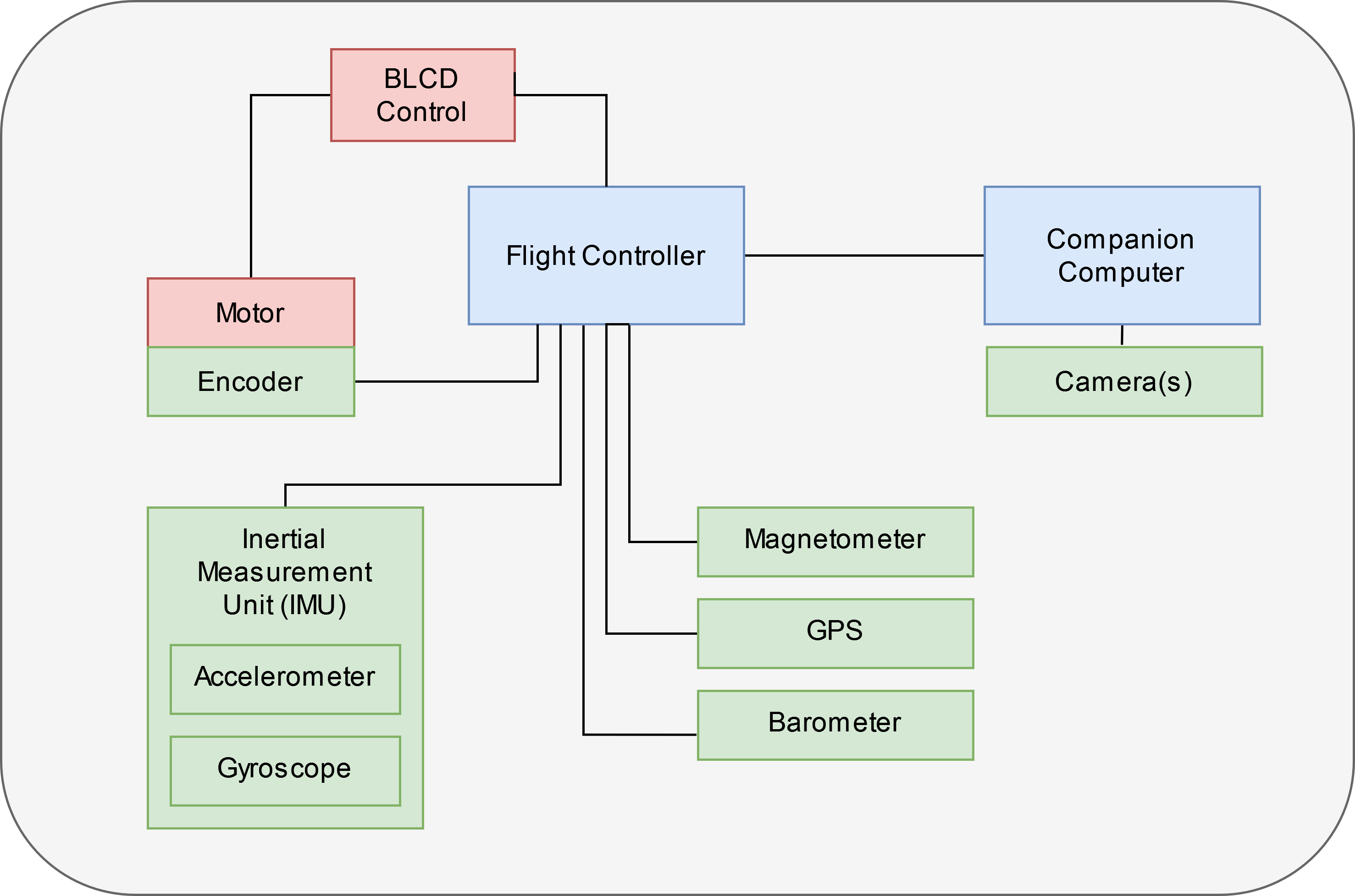
Fig. 1: Electronics top level diagram for the proposed UAV.
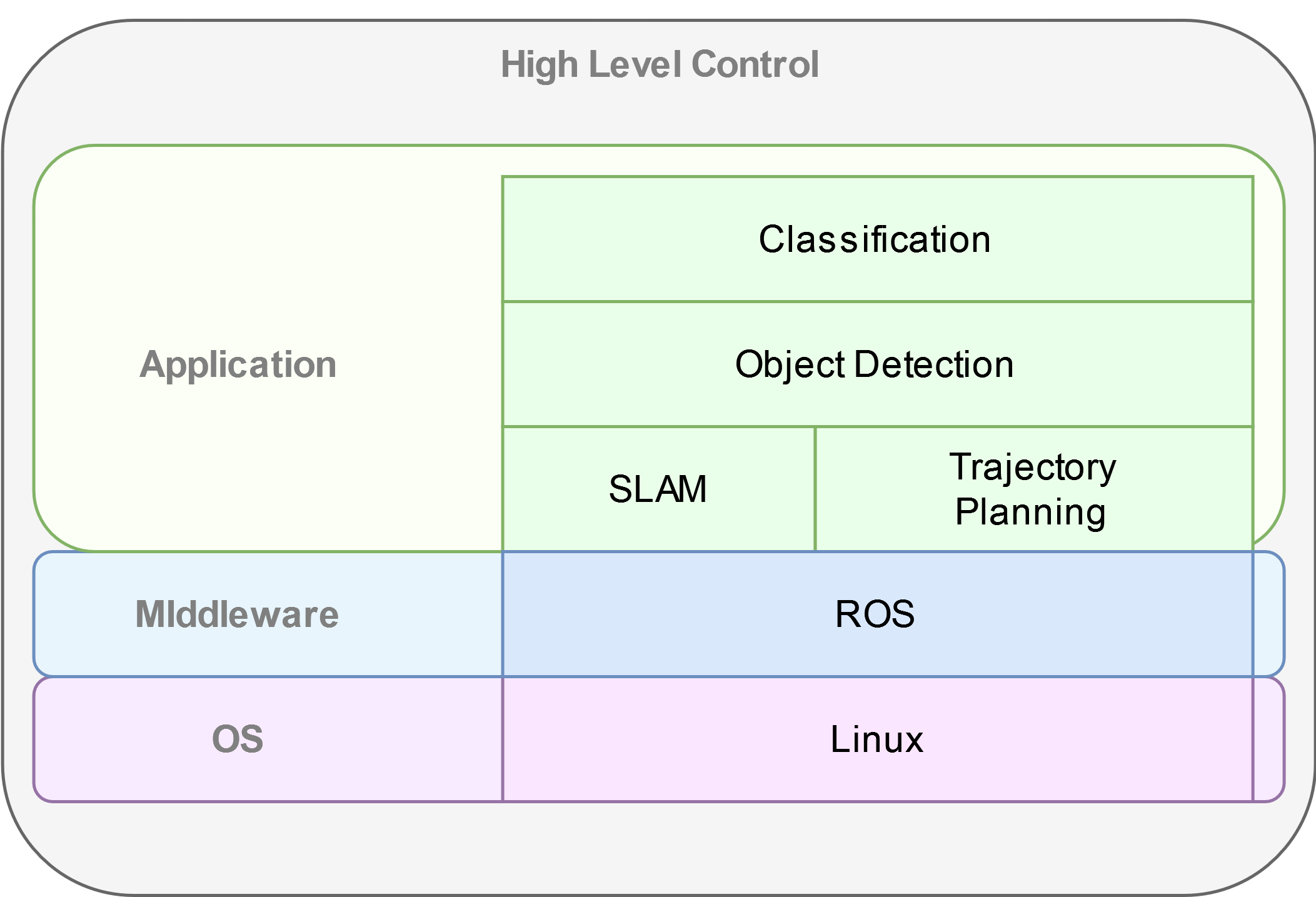
Fig. 2: An example software stack for both the flight controller and the companion computer.
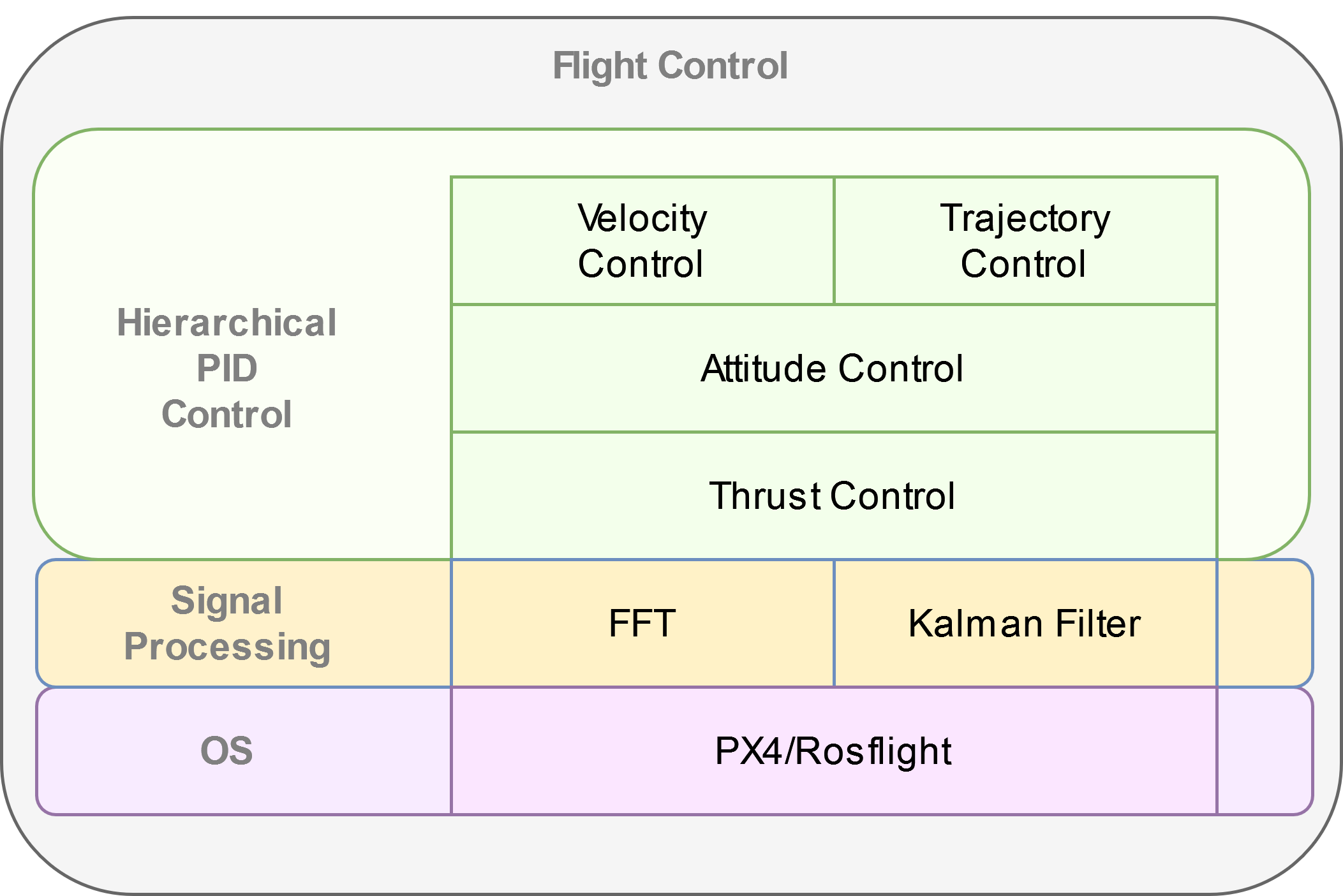
Fig. 2: An example software stack for both the flight controller and the companion computer.
Secondly, a key component of our work involves developing the co-simulation infrastructure for our UAV. Our work builds upon two existing simulators. For simulating UAV dynamics and visual rendering we plan on use the AirSim simulator , based on Unreal Engine developed by Microsoft [13]. For cycle-accurate SoC simulation, we use FireSim, an FPGA-accelerated RTL simulator developed at the ADEPT Lab at UC Berkeley. A top level diagram of our infrastructure is depicted in Figure [5], with components that we expect to make major modifications to highlighted in red. These components mainly consist of the target-to-host bridges found in FireSim, which are responsible for the communication and synchronization between the host CPU managing the RTL simulation, and the target FPGA accelerating the simulation. Our modifications will synchronize the clock cycles elapsed in the RTL simulation with the amount of time simulated in AirSim, as well as to schedule the data transfers between AirSim and the SoC I/O modeled by FireSim. Before moving robotics software to the FireSim simulations, we evaluate the RISC-V ports in a QEMU session as depicted in Figure [4].

Fig. 3: Top level architecture for evaluating ROS workloads on the RISC-V software stack.

Fig. 4: Top level architecture for the proposed co-simulation architecture
The final component of our project involves generating SoC instances on which we evaluate our software stack. For our project, we focus on evaluating custom hardware for an on-board companion computer. This is because the flight controller can be implemented using a low-power microcontroller, and provides no benefit from being accelerated as the frequency of the flight controller loop is bounded by the physical properties of an UAV rather than by the available compute capabilities [12]. On the other hand, accelerating high level control tasks in a HIL setup has been shown to improve quality-of-flight metrics in quadrotors, such as mission time and maximum velocity [10]. Because these high level control tasks run on the companion computer, we identified this unit for our design-space exploration. Developing new custom hardware accelerators is out of the scope of this project. However, we will still work on evaluating configurations of existing hardware, including the in-order Rocket CPU [15], the out-of-order superscalar BOOM CPU [16], and Gemmini, a systolic array hardware generator [17]. We generate hardware designs using these components using Chipyard, an SoC generator developed by the ADEPT Lab at UC Berkeley [18]. While discovering an optimal SoC configuration is out of the scope of this project, we use the designs to evaluate the co-simulation infrastructure.
The project incorporates sensing and actuation through the use of the ASPLOS21-Drone, which acts as a physical reference design for the co-simulation infrastructure. However, sensing and actuation have also be explored through the simulated environment. Similarly, high level control and planning algorithms will be deployed on both the physical and simulated drones.
Physical Drone Implementation
The design was built from commercially avalable parts, and assembled by the team. The overall design is based off of the ASPLOS21-Drone, which provided a build guide and a starting point for reference software. However, the ASPLOS21-Drone did not come with a bill of materials, so some adjustments were made to the construction of the drone compared to the paper. Additionally, to support some of the features needed for indoor flight, several changes had to be made to the software implementation on board the drone.
Bill of Materials
A representation of all the parts needed for the drone are depicted in Figure [5]
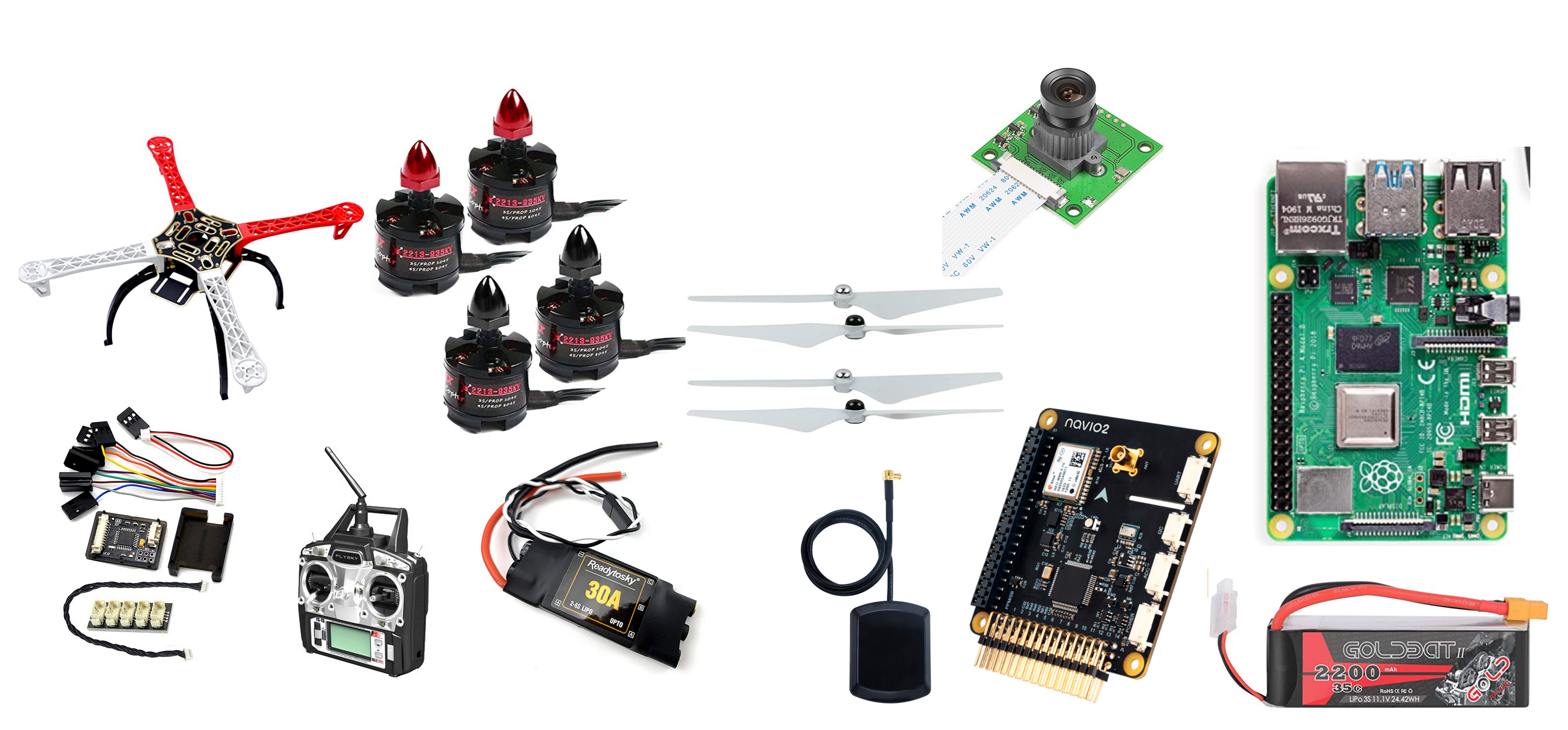
Fig. 5: A breakdown of all parts used to build the drone. From the top left corner going clockwise: F450 Frame, Motors, Propellers, Raspicam, Raspberry Pi 4 B, 3C LiPo Battery, Navio2, GPS, ESC, RC Unit, PPM Encoder
Assembly and Bringup
The drone (named Baby Bird) was assembled following instructions in the BuildGuide of the ASPLOS21-Drone, found here.
Changes compared to the buildguide was the fact that A Raspberry Pi 4 was used instead of a Raspberry Pi 3, the ESCs had built-in bullet connectors, and that a Raspicam was attached to enable vision.
After assembly, the Baby Bird should look as depicted in Figure [6].
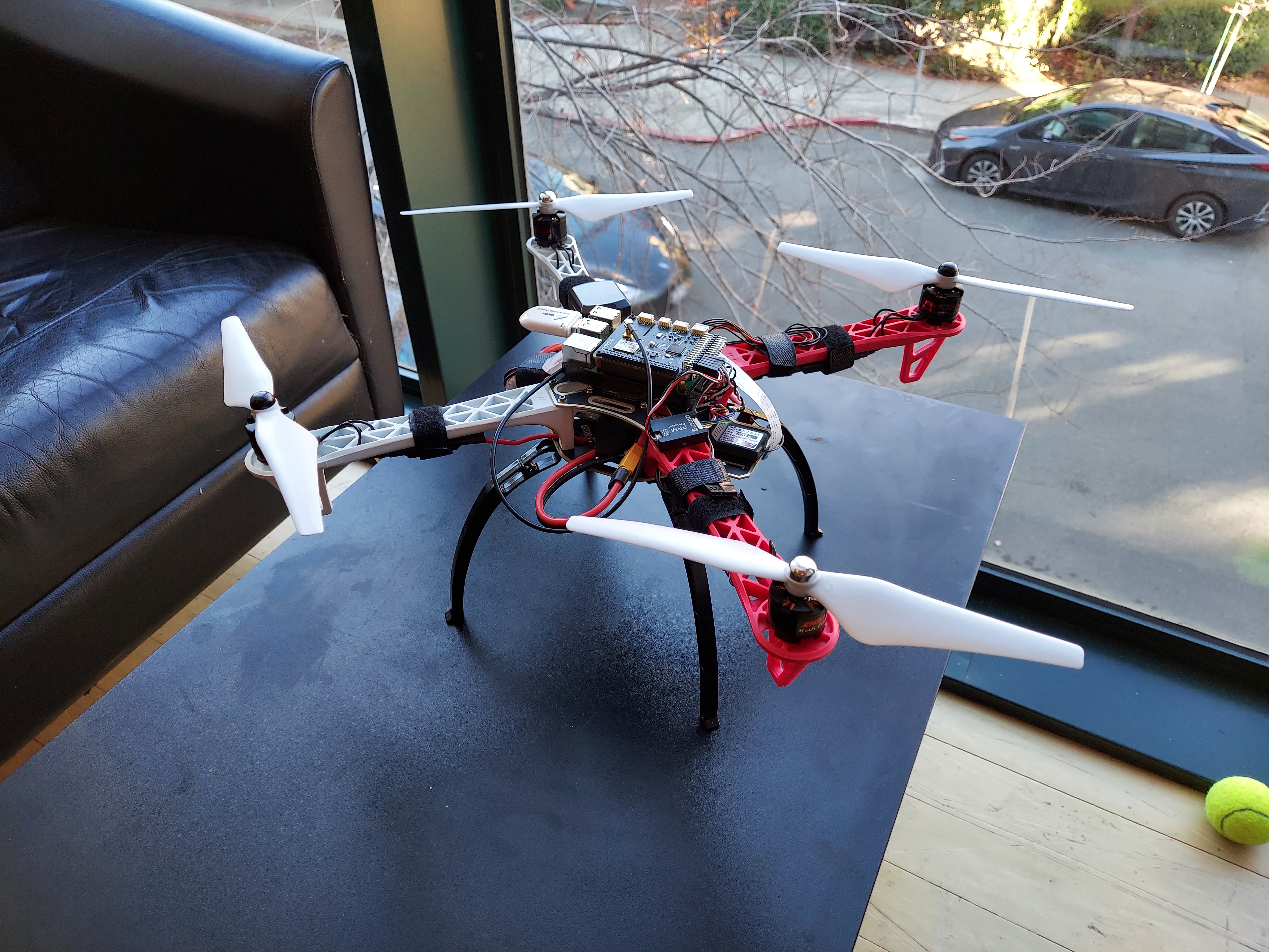
Fig. 6: A top view of Baby Bird, with the battery disconnected and powered off.
Additionally, to build the software infrastructure needed to fly the drone, it is necessary to install Emlid OS, which can be downloaded here.
ROS Infrastructure
ROS is already pre-installed on EmlidOS, but additional ROS libraries need to be installed as needed using the scripts provided at the Navio2 github repository, here. Additionally, the custom ROS code needed to run the project can be found here.
At a high level, the software used in this project interfaces with the system as shown in Figure [7]. The low level control is handled through the flight controller, ArduPilot, while the high level control is handled through mavros, which in turn can connect with other ROS nodes, such as those that handle pose estimation. mavros also directly reads camera data from a ROS topic, while IMU data is read by ArduPilot, which also drives the ESCs. Finally the system can be controlled through the RC unit using MAVLink, or through the ground control station. In this case, mavros also acts as a MAVLink bridge to the ground control station.

Fig. 7: A system level diagram of the ROS nodes interfacing with the system.
A diagram of the TF tree generated by the ROS nodes is depicted in Figure [8], while the ROS graph is depicted in Figure [9].

Fig. 8: The rqt_tree graph showing how the camera frame is connected to the world frame.

Fig. 9: The rqt_tree graph showing how the camera frame is connected to the world frame.
Configuration and Software
To support the newer extended kalman filter options of ArduPilot, it is necessary to build an updated version of ArduPilot from source. To do th is, one can follow the documentation here, using branch Copter-4.1.1. Additionally, one must point /etc/systemd/system/arducopter.service to the updated binary. To setup mavlink and mavros with the right IPs and ports, one can then follow the instructions here.
Next, one needs to run all of the ROS nodes to connect to the ground control station. to do this, one can run the following instructions in separate terminals:
roslaunch mavros apm.launch
cd eecs206a-proj-software && source devel/setup.bash && roslaunch raspicam_node camera_640x480_raw.launch
roslaunch apriltag_ros drone_continuous.launch
rosrun tf static_transform_publisher 0 0 0 0 0 0 tag_0 map 100
cd eecs206a-proj-software && source devel/setup.bash && rosrun drone_test publish_vision_pose.py
The output should look as depicted in Figure [10].
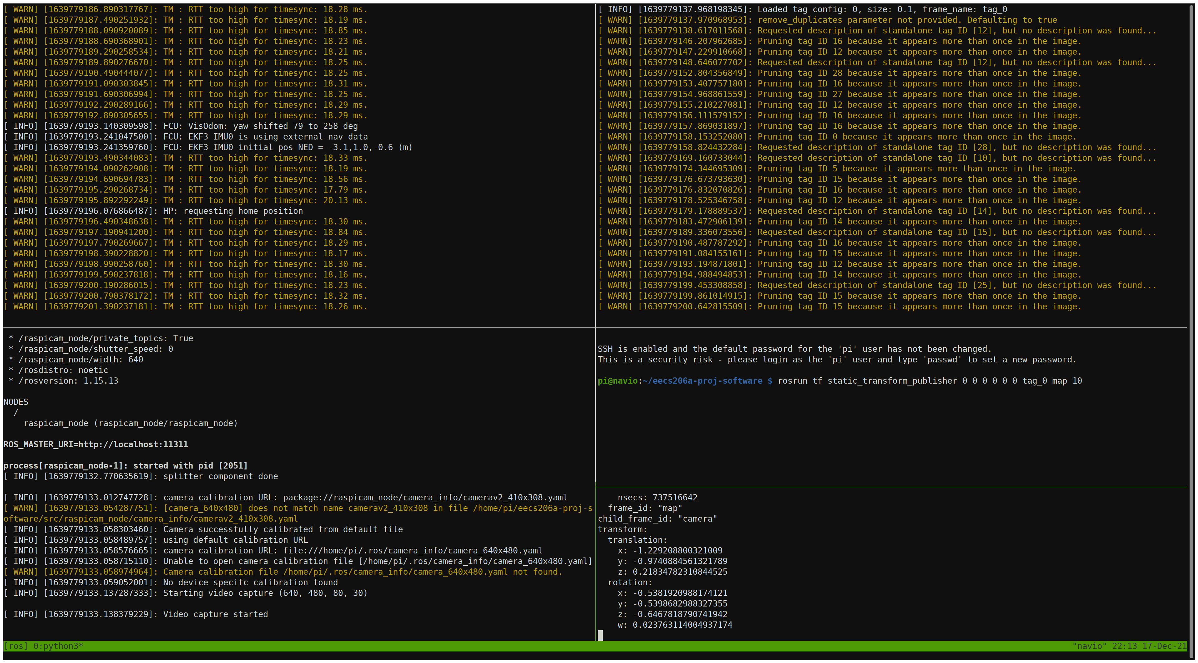
Fig. 10: All necessary ROS nodes running in separate terminal sessions (using tmux).
If this is functional, one can then connect to the drone using a ground control station such as Mission Planner, found here. Once th is is installed, one needs to set the following parameters to set vision based positioning to be the default system. This way only vision is used, without a GPS, which is suitable for indoor flight.
EK3_SRC1_POSXY = 0 (No primary horizontal position)
EK3_SRC1_VELXY = 0 (No primary horizontal velocity)
EK3_SRC1_POSZ = 1 (Primary vertical position from barometer)
EK3_SRC1_VELZ = 0 (No vertical velocity)
EK3_SRC1_YAW = 1 (Primary yaw/heading from compass)
EK3_SRC2_POSXY = 6 (Secondary horizontal position from External Nav)
EK3_SRC2_VELXY = 6 (Secondary horizontal velocity from External Nav)
EK3_SRC2_POSZ = 1 (Secondary vertical position from barometer)
EK3_SRC2_VELZ = 6 (Secondary vertical velocity from External Nav)
EK3_SRC2_YAW = 6 (Secondary yaw/heading from External Nav)
Alternatively, all software can be set up from the pre-built image found here. This just needs to be flashed onto an SD card with the Raspberry Pi.
Co-Simulation Implementation
At a high level the end-goal of the co-simulation infrastructure is to run and integrate both the AirSim and FireSim simulators. For practical purposes, these are deployed on different machines, one running Ubuntu 18.04 for AirSim, and the other running Centos for FireSim. The system can be viewed as in Figure [11]. In this case, AirSim runs on a g4dn.2xlarge instance of AWS, and the FireSim manager runs on a c5.4xlarge instance while the FireSim target simulator runs on a f1.2xlarge instance.

Fig. 11: High-level co-simulation deployment
Installing and Deploying AirSim
- Setting up an AWS instance
Create an AWS account
Setup a login key for your account and download it onto your local machine
Ensure that you have an ssh client installed on your local machine
Navigate to the AWS EC2 Console: https://console.aws.amazon.com/ec2/v2/home?region=us-east-1
Click “Launch Instances”
Under the “AWS Marketplace” tab, select the “Ubuntu 18.04 LTS Desktop - NICE DCV (GPU) with NVIDIA Gaming Drivers” image
For instance type, select a g4dn instance, preferably g4dn.2xlarge
Allocate an EBS volume of at least 200GB
For security, in addition to the default groups add a new rule for a TCP connection with port range 41451, with source 0.0.0.0/0
Launch the instance
- Using NICE DCV to connect to a graphical session
Use ssh to login to your instance
Use sudo dcv list-sessions to view any running sessions
Use sudo dcv close-session [session name] to close any running session
Run sudo dcv create-session –type console airsim
Note that a console session is chosen over a virtual session to avoid vulkan rendering issues
Create a user password by running sudo passwd ubuntu
Download and install the NICE DCV client for your local machine: https://download.nice-dcv.com/
Launch the DCV client and enter your instance’s IP address
Login with your root username and password
Login to the graphical session with ubuntu account.
- Install and test AirSim
Follow the instructions at https://microsoft.github.io/AirSim/build_linux/ for building Airsim on Linux
Set up python controller API
Install pip3 with sudo apt install python3-pip
sudo pip3 install numpy
sudo pip3 install msgpack-rpc-python
sudo pip3 install scikit-build
sudo pip3 install airsim
- Running a simple flight controller
Follow the instructions at https://microsoft.github.io/AirSim/build_linux/ to load the example world, and start a simulation with a drone
Run python3 [AirSim_Dir]/PythonClient/multirotor/hello_drone.py
Follow the prompts and watch the drone fly!
Deploying the AirSim Client in QEMU
First, one must launch a Fedora QEMU RISC-V image using FireMarshal, using documentation found here. Once the virtual machine is launched, one can interactively install the depenencies for AirSim:
sudo apt install python3-pip
sudo pip3 install numpy
sudo pip3 install msgpack-rpc-python
sudo pip3 install scikit-build
sudo pip3 install –no-deps airsim
Once this is done, one can clone the project repository here and run the box_drone.py program from within the QEMU session, passing in the AirSim IP as an argument. A co-simulation is now running with AirSim and QEMU.
Deploying the AirSim Client in FireSim
This step is still a work in progress, and the features are not fully supported. To do this, one must follow the instructions found here and deploy the image generated by FireMarshal from the previous step. Now, one can run AirSim with FireSim, simulating AirSim with a RISC-V SoC modeled in FireSim.
Porting ROS1 for RISC-V
The guide for setting up the core ROS Noetic libraries for RISC-V is shown below. This requires building many dependencies manually. The platform used here is a RISC-V Fedora image as found in FireMarshal, and was excuted in QEMU:
sudo dnf install gcc-c++ python3-rosdep python3-rosinstall_generator python3-vcstool @buildsys-build
sudo rosdep init
rosdep update
wget https://pari.math.u-bordeaux.fr/pub/pari/unix/pari-2.13.1.tar.gz
tar -xvf pari-2.13.1.tar.gz
[ install pari ]
dnf install libsvm fcgi ffcall libglade2 libpq
rpm -i clisp-2.49.93-14.c26de78git.fc33.riscv64.rpm –nodeps
[ remove roslisp, genlisp entry from rosinstall file ]
git clone git://git.code.sf.net/p/sbcl/sbcl
cd sbcl
sh make.sh /usr/bin/clisp
sh install.sh
cd ..
mkdir ~/ros_catkin_ws
cd ~/ros_catkin_ws
rosinstall_generator ros_comm –rosdistro noetic –deps –tar > noetic-comm.rosinstall
mkdir ./src
vcs import –input noetic-comm.rosinstall ./src
[ remove genlisp from src/catkin/test/network_tests/test.rosinstall, src/catkin/test/checks/test-nocatkin.rosinstall, src/message_generation/CMakeLists.txt ]
Comment <run_depend>sbcl</run_depend> in src/roslisp/package.xml
rosdep install –from-paths ./src –ignore-packages-from-source –rosdistro noetic -y
After this is done, one will have a RISC-V environment supporting ROS1 Noetic as shown in Figure [12]
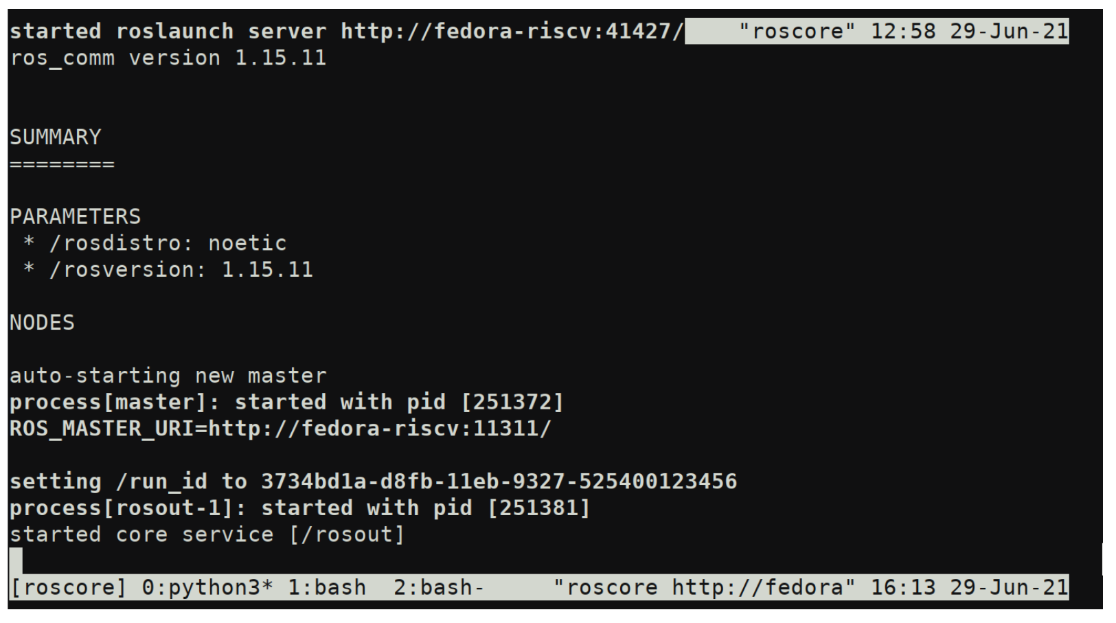
Fig. 12: ROS Noetic running in Feodra on RISC-V
Tasks, Milestones, and Assessment
This project includes a broad range of tasks, and relies heavily on infrastructure development. Accounting for this, we have not accomplish every task, given that there might be unexpected issues related with third-party components. We divide the tasks into Base, Target, and Reach, where we completed base tasks by mid November, Target tasks by the project deadline, and Reach tasks if time permits. As this is a continuing research project, we plan on continuing this infrastructure development after the semester ends.
We will assess the success of this project both on the milestones met, but also by the documentation and analysis of areas of improvement in the robotics, open source hardware, and electronic design automation communities that we encounter while working on this project.
Physical UAV Prototyping
(Base) Obtain FAA licenses and register drone: Needed to legally pilot drones for recreational/research purposes. Can be filed online.
(Base) Assemble ASPLOS21-Drone: Purchase the parts listed in the BOM and follow the assembly instructions as in the ASPLOS21-Drone BuildGuide. Ensure that the drone functions using manual controls.
(Base) Deploy flight controller: Deploy ArduPilot onto the drone hardware, and verify that it can perform takeoff/landing as well as waypoint tracking.
(Target) Develop basic high level control in ROS: Deploy algorithms including mapping, localization, perception, and trajectory planning.
(Reach) Evaluate UAV performance: Verify that the system displays expected functionality, and note potential improvements.
(Reach) Optimize high level control in ROS: Make improvements to algorithms and scheduling to improve system-level performance.
Porting ROS libraries to RISC-V
(Base) Port core ROS middleware: Ensure that core ROS libraries are functional when compiled for RISC-V, demonstrating functionality of a ROS master as well as roscpp or rospy.
(Target) Port integration-level libraries: Ensure that standard or commonly used libraries such as sensor_msgs, geometry_msgs and tf2 function properly.
(Reach) Port application-level libraries: Build and verify the functionality of libraries such as MoveIt, gmapping, and OpenCV.
Developing Co-simulation Infrastructure
(Base) Interface with AirSim from QEMU session: Transmit waypoints to AirSim from a RISC-V QEMU session, and receive sensor data through the AirSim APIs.
(Target) Integrate ROS in QEMU with AirSim: Run ROS code ported to RISC-V running high-level control, deploying setpoints to and reading sensor data from AirSim.
(Target) Interface with AirSim from FireSim: Transmit waypoints to and receive sensor data from AirSim from a simulated SoC within FireSim.
(Reach) Integrate ROS on FireSim with AirSim: Run ROS code on FireSim, communicating with AirSim.
(Reach) Implement lockstep time synchronization between AirSim and FireSim: Create a synchronizer bridge between FireSim and Airsim, using custom hardware to ensure lockstep synchronization between AirSim frames and FireSim cycles.
(Reach) Implement deterministic data synchronization between Airsim and FireSim: Implement a system for scheduling and releasing data transfers at deterministic time intervals between AirSim and FireSim, stalling simulation in case of unexpected network delays.
Generating Robotics SoC Designs in Chipyard
(Base) Single Rocket Core: Generate hardware using a single Rocket in-order CPU.
(Target) Multi-core Rocket: Generate hardware with 4-8 Rocket cores.
(Target) Single BOOM Core: Generate hardware using a BOOM out-of-order superscalar CPU.
(Reach) Heterogeneous Rocket/BOOM SoC: Generate design with both high performance BOOM cores and efficient Rocket cores.
Documenting Challenges
Software Challenges: Did any of the software/algorithms not work as expected? Are there any potential improvements?
Software Infrastructure Challenges: Are there any missing libraries or tools that prevent porting some software libraries to RISC-V? Are there deficiencies with simulators impacting integration for co-simulation?
Hardware Challenges: Do existing configurations face significant bottlenecks for the given workloads?
Hardware Infrastructure Challenges: Are there missing features/IP that impact the ability to port applications to RISC-V? Are there limitations of FPGA-accelerated simulations that impact co-simulation performance?
Unexpected Issues: Any other legal/social/mechanical/etc. concerns?
Items for physical prototyping
We use the ASPLOS21-Drone to perform physical prototyping for this project. This project involves purchasing components for physical prototyping, as well as paying for the use of AWS infrastructure for software development and running GPU and FPGA accelerated simulations. Additionally, we also use the following AWS EC2 instances using on-demand pricing: c5.4xlarge (Managing FireSim simulations, general software development), g4dn.2xlarge (Running GPU-accelerated drone simulations using AirSim), and f1.2xlarge (Running FPGA-accelerated RTL simulations in FireSim.)
Results
First, the first manual flight of Baby Bird is shown below:
Next, the demo of the Apriltag detection is shown below, as well as the tracking in RViz is shown below:
Finally, the final flight of Baby Bird is shown here, with an attempt at tracking the Apriltag is shown below:
For the co-simulation aspect, an example where the drone is being simulated in AirSim and controlled through RISC-V QEMU is shown below:
Conclusion
Overall, while it was possible to implement all the base requirements for the project, doing so was much more challenging than expected. To begin with, there were a lot of seperate peices of infrastructure that needed to be intergrated, which needed to use a completely different set of APIs and systems:
Unreal Engine (Unreal API)
AirSim (AirSim RPC API)
RISC-V QEMU (FireMarshal, Fedora)
FireSim (FPGA flows, Chisel HDL, Bridges and Bridge Drivers)
ROS (mavros, MAVLink, raspicam)
ArduCopter (MAVLink, PPM)
AWS EC2 instances
And each required its own setup and build guide, as well as deployment. Some additional unexpected challenges involved configuring ArduPilot/ArduCopter using MAVLink, as the particular sensing configuration we were using was not officially documented. Additionally, we did not have good GPS signals in indoor flights, so we did not have a fallback we could use that would work by default. Finally, during the last week of the project AWS had a major outage in the region that we were using for our EC2 instances. This demonstrated the amount of dependencies in our environment, and the challenges that one would face if there were any issues in each domain.
However, despite all this we were still able to deploy all of the base requirements that we had planned. In terms of the physical prototyping we successfully assembled Baby Bird, and had working flight controller integrated with basic high level control in ROS. Second, we were able to port the core ROS Noetic libraries to RISC-V. Next, we were able to interface AirSim with QEMU, and made images to deploy to FireSim. Finally, we were able to build multi-core Rocket designs using Chipyard for sinulating our workloads. Finally, we were able to document the steps and challenges we faced along the way while trying to set up the infrastructure.
We plan to use this project as a baseline for doing our co-simulation and design-space-exploration work for our future research. To continue to improve the project, we plan to have a more polished automated flow for deploying the project, rather than manually having to follow each setup guide listed in this document. Additionally, we plan to continue to develop our support for ROS so we can actually run meaningful workloads in QEMU and FireSim. Next, we plan to do measurements on Baby Bird to get latency readings for I/O and memory that we will use as references for our simulated communication. Finally, we plan to use this infrastructure to pick a design point for a RISC-V SoC, and target our design for a tapeout in the next year.
Team
Dima Nikiforov
Dima is in charge of tasks involving porting software libraries to RISC-V, developing FireSim to support co-simulation, and generating hardware designs, given their experience working with similar infrastructures and environments at the ADEPT Lab.
- Education:
– Graduate: PhD in Electrical Engineering and Computer Sciences at UC Berkeley (In progress) – Undergraduate: BS in Computer Engineering and BA in Philosophy from Purdue University
- Work Experience:
- – Bendix Commercial Vehicle Systems (1.5 Years)
Embedded Systems Design
Advanced Driver Assistance Systems
Systems Engineering
- – Advanced Micro Devices (3 months)
Design Verification Engineering
- Research Experience:
- – ADEPT Lab @ UC Berkeley
Design and integration of hardware accelerators in heterogeneous SoCs
- – AALP @ Purdue University
Locality aware data management for multi-GPU systems
- – SoCET @ Purdue University
Custom hardware extensions for accelerating machine learning on an embedded processor
- – CAM2@ Purdue University
Computer vision for pedestrian detection on JPEG compressed data
- – Purdue Aerial Robotics @ Purdue University
PCB design for a flight controller board and a ground station antenna tracker
Chris Dong
Chris is in charge of developing the software infrastructure via ROS and AirSim, setting up AirSim in AWS server and running built-in simple flight controller, along with developing and testing high level algorithms both in simulation and on the real drone.
- Education:
– Graduate: PhD in Electrical Engineering and Computer Sciences at UC Berkeley (In progress) – Undergraduate: BS in Computer Science, BS in Mathematics, and BBA in Finance from UMass Amherst
- Work Experience:
- – Amazon AWS: Project Manager@Robotics Lab
Coordinated full project-development lifecycle at Amazon AWS Robotics lab: strategic planning, requirements analysis, testing, and product launches.
- – Tesla: Application Developer Intern
Developing an enterprise consumer-facing mobile application on Android in React Native enabling remote control on vehicles.
Designing and implementing a content management system and user database for the IT Application Development Team
- – 3R Water, Inc: Software Developer
Developed an enterprise climate-technology software and data platform on Android platforms for municipal stormwater agencies to address flooding and water quality issues and build climate resiliency.
Collaboration
While we collaborating throughout the project in general, we have made sure to only do drone hardware prototyping and testing when both group members are present in order to follow lab safety protocols. We also collaborate heavily to ensure that we can successfully integrate the infrastructure components that we develop.
Additional Materials
Code repositories and disk images are found in the implementation section.
References
[1] L. K. Scheffer, “The physical design of biological systems-insights from the fly brain,” in Proceedings of the 2021 International Symposium on Physical Design, 2021, pp. 101–108.
[2] A. Suleiman, Z. Zhang, L. Carlone, S. Karaman, and V. Sze, “Navion: A 2-mw fully integrated real-time visual-inertial odometry accelerator for autonomous navigation of nano drones,” IEEE Journal of Solid-State Circuits, vol. 54, no. 4, pp. 1106–1119, 2019.
[3] J. L. Hennessy and D. A. Patterson, “A new golden age for computer architecture,” Communications of the ACM, vol. 62, no. 2, pp. 48–60, 2019.
[4] Z. Wan, B. Yu, T. Y. Li, J. Tang, Y. Zhu, Y. Wang, A. Raychowdhury, and S. Liu, “A survey of fpga-based robotic computing,” 2021.
[5] R. Li, X. Huang, S. Tian, R. Hu, D. He, and Q. Gu, “Fpga-based design and implementation of real-time robot motion planning,” in 2019 9th International Conference on Information Science and Technology (ICIST). IEEE, 2019, pp. 216–221.
[6] B. Chr ́etien, A. Escande, and A. Kheddar, “Gpu robot motion planning using semi-infinite nonlinear programming,” IEEE Transactions on Parallel and Distributed Systems, vol. 27, no. 10, pp. 2926–2939, 2016.
[7] J. Liang, V. Makoviychuk, A. Handa, N. Chentanez, M. Macklin, and D. Fox, “Gpu-accelerated robotic simulation for distributed reinforce- ment learning,” in Conference on Robot Learning. PMLR, 2018, pp. 270–282.
[8] S. Murray, W. Floyd-Jones, Y. Qi, G. Konidaris, and D. J. Sorin, “The microarchitecture of a real-time robot motion planning accelerator,” in 2016 49th Annual IEEE/ACM International Symposium on Microarchi- tecture (MICRO). IEEE, 2016, pp. 1–12.
[9] S. Lian, Y. Han, X. Chen, Y. Wang, and H. Xiao, “Dadu-p: A scalable accelerator for robot motion planning in a dynamic environment,” in 2018 55th ACM/ESDA/IEEE Design Automation Conference (DAC). IEEE, 2018, pp. 1–6
[10] B. Boroujerdian, H. Genc, S. Krishnan, W. Cui, A. Faust, and V. Reddi, “Mavbench: Micro aerial vehicle benchmarking,” in 2018 51st Annual IEEE/ACM International Symposium on Microarchitecture (MICRO). IEEE, 2018, pp. 894–907.
[11] J. Delmerico, T. Cieslewski, H. Rebecq, M. Faessler, and D. Scaramuzza, “Are we ready for autonomous drone racing? the uzh-fpv drone racing dataset,” in 2019 International Conference on Robotics and Automation (ICRA). IEEE, 2019, pp. 6713–6719.
[12] R. Hadidi, B. Asgari, S. Jijina, A. Amyette, N. Shoghi, and H. Kim, “Quantifying the design-space tradeoffs in autonomous drones,” in Proceedings of the 26th ACM International Conference on Architectural Support for Programming Languages and Operating Systems, ser. ASPLOS 2021. New York, NY, USA: Association for Computing Machinery, 2021, p. 661–673. [Online]. Available: https://doi.org/10.1145/3445814.3446721
[13] S. Shah, D. Dey, C. Lovett, and A. Kapoor, “Airsim: High-fidelity visual and physical simulation for autonomous vehicles,” in Field and service robotics. Springer, 2018, pp. 621–635.
[14] S. Karandikar, H. Mao, D. Kim, D. Biancolin, A. Amid, D. Lee, N. Pemberton, E. Amaro, C. Schmidt, A. Chopra, Q. Huang, K. Kovacs, B. Nikolic, R. Katz, J. Bachrach, and K. Asanovic, “Firesim: Fpga- accelerated cycle-exact scale-out system simulation in the public cloud,” in 2018 ACM/IEEE 45th Annual International Symposium on Computer Architecture (ISCA), 2018, pp. 29–42.
[15] K. Asanovic, R. Avizienis, J. Bachrach, S. Beamer, D. Biancolin, C. Celio, H. Cook, D. Dabbelt, J. Hauser, A. Izraelevitz et al., “The rocket chip generator,” EECS Department, University of California, Berkeley, Tech. Rep. UCB/EECS-2016-17, 2016.
[16] J. Zhao, B. Korpan, A. Gonzalez, and K. Asanovic, “Sonicboom: The 3rd generation berkeley out-of-order machine,” in Fourth Workshop on Computer Architecture Research with RISC-V, 2020.
[17] H. Genc, S. Kim, A. Amid, A. Haj-Ali, V. Iyer, P. Prakash, J. Zhao, D. Grubb, H. Liew, H. Mao et al., “Gemmini: Enabling systematic deep- learning architecture evaluation via full-stack integration,” in Proceed- ings of the 58th Annual Design Automation Conference (DAC), 2021.
[18] A. Amid, D. Biancolin, A. Gonzalez, D. Grubb, S. Karandikar, H. Liew, A. Magyar, H. Mao, A. Ou, N. Pemberton, P. Rigge, C. Schmidt, J. Wright, J. Zhao, Y. S. Shao, K. Asanovi ́c, and B. Nikoli ́c, “Chipyard: Integrated design, simulation, and implementation framework for custom socs,” IEEE Micro, vol. 40, no. 4, pp. 10–21, 2020.
[19] “Dromajo,” 2021. [Online]. Available: https://github.com/chipsalliance/ dromajo
[20] M. Acevedo, “Fpga-based hardware-in-the-loop co-simulator platform for systemmodeler,” 2016.
[21] K. Rozhdestvensky, V. Ryzhov, T. Fedorova, K. Safronov, N. Tryaskin, S. A. Sulaiman, M. Ovinis, and S. Hassan, “Description of the wolfram systemmodeler,” in Computer Modeling and Simulation of Dynamic Systems Using Wolfram SystemModeler. Springer, 2020, pp. 23–87.
[22] S. Acharya, A. Bharadwaj, Y. Simmhan, A. Gopalan, P. Parag, and H. Tyagi, “Cornet: A co-simulation middleware for robot networks,” in 2020 International Conference on COMmunication Systems & NET- workS (COMSNETS). IEEE, 2020, pp. 245–251.
Acknowledgements
This material is based upon work supported by the National Science Foundation under Grant No. (CCF-1955450). Any opinions, findings, and conclusions or recommendations expressed in this material are those of the authors and do not necessarily reflect the views of the National Science Foundation.
This project was, in part, funded by the U.S. Government under the DARPA RTML program (contract FA8650-20-2-7006). The views and conclusions contained in this document are those of the authors and should not be interpreted as representing the official policies, either expressed or implied, of the U.S. Government.